Subaru Ignition Coil Wiring Diagram
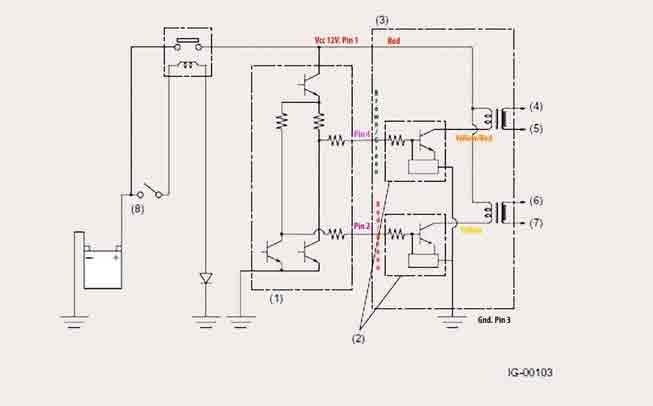
A Subaru ignition coil wiring diagram shows the electrical connections between each of the coils and the spark plugs. It also shows how to connect these components together, as well as where certain wires should be connected. The diagram will typically include a list of what type of wire is used for each connection.
subaru tribeca ignition coil wiring diagram
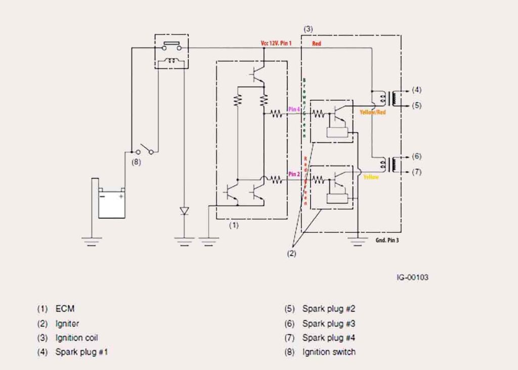
ignition coil diagram
Additionally, it may provide information about any fuses or relays that are necessary for the proper operation of the vehicle’s ignition system. If you need help understanding a wiring diagram, consult your vehicle’s owner manual or contact an automotive technician with experience in repairing Subarus.
Read More About Subaru Ej255 Vacuum Diagram
How To Check Subaru Ignition Coil
- Locate the ignition coils on your Subaru engine and remove the spark plug wires from them
- In most cases, these will be located near the top of the engine bay and will have four spark plug wires connected to them
- Disconnect the power supply to each coil by unplugging its electrical connector or disconnecting its ground wire depending on how it is wired in your vehicle’s system
- Test each coil using an ohmmeter set to measure the resistance across a range of 0-20k ohms for automotive applications
- Place one probe on each terminal of the ignition coil and note any readings that are significantly different from other coils as this may indicate an issue with that particular unit requiring replacement or repair if possible
- Check for arcing or sparks coming from within the casing when running at higher RPMs if you suspect a faulty coil due to inconsistent readings but no obvious breaks in insulation or damage visible externally (this can occur even without any significant differences between reading results)
- Replace any coils which show signs of wear, damage, arcing internally or consistently read outside their normal range according to manufacturer specifications before reassembling all components back into place securely and reconnecting power supplies accordingly as necessary
how to wire an ignition coil diagram
- Read the Ignition Coil Wiring Diagram: Before beginning any wiring project, it is important to understand exactly what the diagram contains and how it relates to the ignition coil is installed
- It is also necessary to identify each component in order to properly connect them together
- Gather Supplies and Tools: To install an ignition coil, you will need a few basic tools including wire strippers, electrical tape, a soldering iron, heat shrink tubing, and screws or bolts for attaching components securely
- In addition, make sure all of the hardware that came with your ignition coil is present before beginning so nothing needs to be ordered afterward
- Connect Primary Wires: The primary wires are usually red and black; these should be connected directly from the battery power source through a fuse holder or relay switch (with correct amperage rating) into primary posts on coil housing according to the diagram provided with the product instructions or diagram printed on side of unit itself if available
- Make sure connections are secure using the appropriate size screwdriver/nut driver as needed and insulated by taping off exposed metal contact points for safety reasons 4
- Connect Secondary Wires: Once primary wires have been successfully connected, the next step involves connecting secondary wires which typically range between 8-12 gauge depending on application requirements
- These should be routed from the spark plug end towards the distributor cap following the same route taken by high tension cables attached thereto (if applicable)
- Securely attach ring terminals onto both ends of the wire then solder connection points where applicable
- Insulate the entire length with electrical tape once completed 5 Attach Ground Wire: Lastly, ensure the ground wire has been properly wired up prior to testing the system out – this should come from the engine block or frame and then looped around the bolt securing the bottom part of the mounting bracket before being secured tightly against mount point via nut/bolt combination
Also Read: Best True Dual Exhaust
About Coil Wiring
Coil wiring is the process of connecting electrical components in a circuit to create an electric current. It involves running wires through insulation and wrapping them around a core, such as copper or aluminum.
The purpose of coil winding is to make sure that electrical signals can travel smoothly from one component to another without interference or disruption.
What is the Difference between Single-Coil And Double-Coil Wiring
Single-coil wiring is a type of electrical wiring in which one wire wraps around the pickup’s magnetic pole pieces, creating an electromagnetic field that generates sound when vibrated.
Double-coil wiring involves two wires wrapped around the pickup, usually separated by a steel plate or bobbin. This produces a higher output signal than single-coil pickups because both coils are working together to generate greater volume and clarity for your sound.
The double-coil setup also offers more tonal options than single-coils with its ability to create humbucker sounds as well as split-coil tones.
What are the Benefits of Using a Coil Wired System
Using a coil-wired system is an excellent way to ensure maximum efficiency and reliability when it comes to energy consumption. This type of system has several advantages, including increased safety, improved cost-effectiveness, reduced energy losses, and better performance over extended periods.
As the wiring of the coils is arranged in series or parallel configurations, they help reduce voltage drops in long runs while increasing overall current capacity.
Coil-wired systems also reduce labor costs as there is no need for rewiring due to changes in load requirements or short circuits. Furthermore, coil-wired systems have been found to be more reliable than other types of wiring because they do not suffer from physical damage caused by vibration or corrosion as traditional cables do.
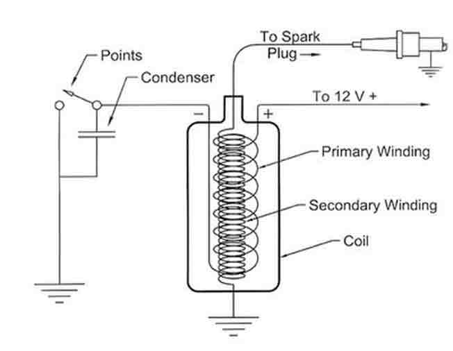
What Wires Go To The Ignition Coil
The ignition coil consists of two wires. One wire is the primary winding, which receives power from the vehicle’s battery, and the other is the secondary winding, which sends power to the spark plug. The primary winding usually has a low voltage (6-12 volts) that comes directly from the car’s ignition switch or battery.
The secondary winding typically has a much higher voltage (20k-30k volts) that goes to each individual spark plug. Both windings must be connected correctly in order for an engine to run properly; otherwise, it will not start or perform as expected.
When these three wires are connected correctly, they ensure that your car’s engine gets enough voltage for proper combustion and efficient running.
Q1: Where Can I Find a Subaru Ignition Coil Wiring Diagram
A Subaru ignition coil wiring diagram can be found in a service manual specific to the vehicle model or year. It is also possible to find it online on various websites such as SubaruPartsDeal.com and CarParts.com, both of which offer detailed diagrams for all models of Subarus.
Additionally, there are many videos available on YouTube that provide step-by-step instructions for how to install an ignition coil in a specific Subaru model, including diagrams and illustrations.
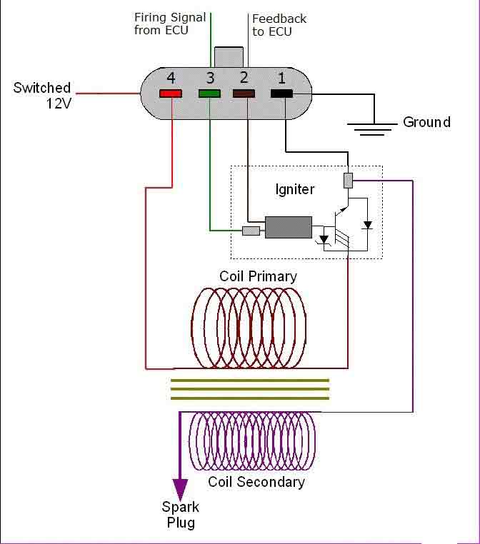
4-wire ignition coil diagram
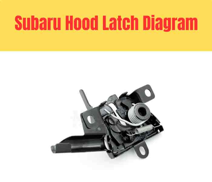
Read Also Subaru Hood Latch Diagram
Q2: What Do the Different Colors Mean in a Subaru Ignition Coil Wiring Diagram
The different colors in a Subaru ignition coil wiring diagram can have various meanings. Generally, the red wire is used as the primary power source and typically connects to the positive terminal of the battery. The black wire is usually connected to the ground and serves as a return path for the current flow.
The yellow wire may be an auxiliary or switched power supply, while other colored wires can provide additional control signals for electronic components such as sensors, solenoids, switches, and relays.
Additionally, blue wires are often used to connect two points together (e.g., from one component to another), while green wires are usually responsible for connecting more than two devices together in order to complete a circuit.
FAQ
How Do You Test a Subaru Coil Pack With a Multimeter?
Testing a Subaru coil pack with a multimeter is relatively straightforward. First, set the multimeter to measure resistance (ohm) and then disconnect the coil pack from its connector. Then take both probes of the multimeter and place them on either side of the spark plug terminal connected to the coil pack.
If you get an open circuit or no reading, this means that there is an issue with your coil pack and it needs to be replaced. If you do get a reading, compare it against manufacturer specifications listed in your vehicle’s service manual for accuracy and make sure that it matches up correctly before reattaching your coil pack back into place.
How Do You Check an Ignition Coil to See If It’s Good?
To check if an ignition coil is good, you should first test its resistance with a multimeter. You should connect the leads of the multimeter to each terminal of the ignition coil and measure the voltage reading. If it falls within the manufacturer’s specified range, then your coil is likely in good condition.
Additionally, another way to check if an ignition coil is functioning properly is by performing a visual inspection. Look for any signs of corrosion or damage on both terminals and any wires connecting them to other components.
Finally, pay attention to how quickly spark plugs are firing when cranking up your engine as this can indicate whether or not your ignition coils are working correctly.
How Do I Know Which Ignition Coil is Out?
In order to determine which ignition coil is out, you should first check the spark plugs for signs of damage or wear. When a spark plug fails, it usually leaves behind evidence such as black carbon deposits on the electrodes and core nose. If one of your spark plugs appears worn or damaged, then you can suspect that its corresponding ignition coil has failed.
Another sign of faulty ignition coils could be misfiring cylinders which can be detected with an engine diagnostic scan tool.
Furthermore, if there are visible cracks in the insulation or exterior casing around the ignition coil itself then this could also indicate a fault.
How Do I Know If My Subaru Coil Pack is Bad?
A bad coil pack can cause a variety of issues with your Subaru’s engine, including misfiring, poor acceleration, and decreased fuel economy. You may also notice that the check engine light is illuminated on your dashboard. Other signs of a failing coil pack are an abnormally loud or rough idle and longer crank times when starting the vehicle.
Conclusion
This blog post provided an in-depth look at the Subaru ignition coil wiring diagram, highlighting its various components and how they work together. It also discussed the importance of properly connecting all parts to ensure a safe and reliable electrical system.